Technology options towards a Zero Trust network

In a previous article I explained what Zero Trust (ZT) is about and I positioned it in the overall context of the changing cybersecurity landscape.

This article summarizes the different techniques to enable enterprise networks for ZT. It is important to understand that the enterprise’s strategy for ZT shall drive technology adoption, rather than the reverse. That being said, in most cases, an organization does not need to start ZT from scratch. It is likely that there are already processes and technology adopted that can be taken to a next level, in order to reach the ZT objective.

Foundation for a ZT ready network: dynamic, identity-based access policy and micro-segmentation

Let me start with a brief recall of the main principles of a ZT network.

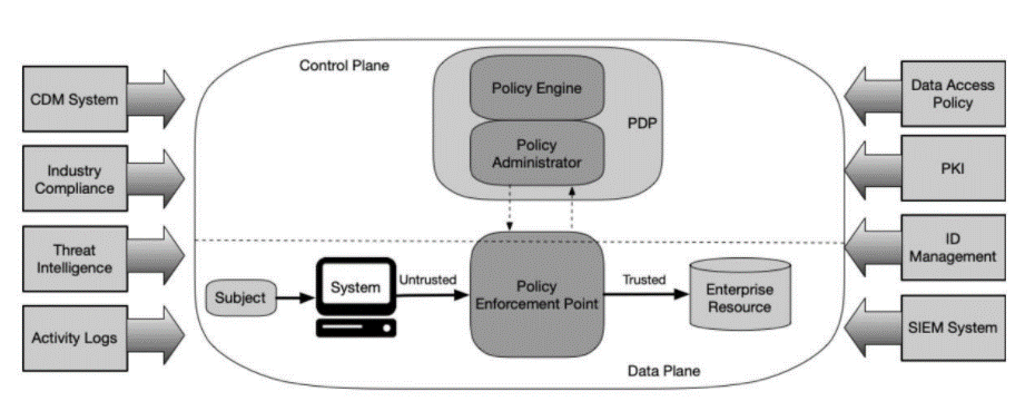
(1) Dynamic, identity-based access policy grants a requester (a ‘subject’ in the vocabulary of National Institute of Standards and Technology, NIST) network access to a resource, no longer by trusting its IP address or subnet, but after checking its identity or profile. Upon its connection attempt, the identity or other characteristics of the requester (user, device or resource) is signaled to a central authentication and authorization service, which acts as Policy Decision Point (PDP). If there is a match (e.g. the credentials of the user on the device are valid or the device’s profile is recognized), PDP dynamically assigns its policy, determining which resources this subject is allowed to access. This dynamic recognition and policy assignment abstract policy from any network construct, like was the case with access policies based on traditional network segmentation by routing instances or VRFs and LAN-segments or VLANs.

(2) Micro-segmentation contains resources in fine-grained, logical groups residing inside or even across the existing network constructs. This improves control of lateral flows, hence reduces the attack-surface of traditional macro-segments. Also, micro-segments decouple security segmentation from any network construct, which usually defines a traditional macro-zone. This makes it possible to define segments following logical criteria, like user groups and roles, device types, application affinities and more.

Synergizing both above principles drastically reduces the burden of adding or moving endpoints. There is no more need for any updates in the network and on firewalls. These updates are known as labor intensive, error-prone, hence often cause long delays before new workloads and applications can be deployed and made available for use.

(3) a ZT model continuously monitors, controls, logs and audits user activity in real time. This provides organizations with a complete picture of who accesses what, and why. When suspicious activity occurs, security teams receive immediate warnings, making it easy to identify and respond to potentially malicious activity.

Identity based access policy

This comes to authorizing a requester to access resources on the network, based on the his identity or profile, rather than on his location in the network. Hence, policies and corresponding rules shall base permissions on user groups or other attributes pertinent to the requester, rather than on IP addresses.

The traditional method to authenticate endpoints to wired or Wi-Fi LAN consists in the IEEE 802.1x standard, using RADIUS as authentication service. Typically, RADIUS is backed by the enterprise’s identity directory service, most often Windows Active Directory (AD). Hereby, the wired or Wi-Fi network access device (switch or wireless access point, respectively) polls the connecting endpoint for its credentials like userid/password or certificate, and forwards these to RADIUS. Upon endpoint authentication, RADIUS acts as Policy Decision Point (PDP) and links the device identity to the segment the device shall be part of, more precisely to its VLAN-id. It returns the VLAN-id as a RADIUS attribute to the network access device. The network access device then dynamically configures the switchport accessed by the authenticated device into the right VLAN.

Beyond IEEE 802.1x authentication based upon endpoint credentials, network vendors enriched authentication criteria by more device specific attributes like MAC address, system name, OS(-version), manufacturer etc. With this technique, most often known as ‘device profiling’, PDP first tries to discover the endpoint’s attributes, then authorizes the endpoint when its attributes match a valid profile and subsequently, instruct the network access to place the endpoint into the VLAN assign to the profile.

Although organizations applying IEEE 802.1x, maybe extended by ‘profiling’, decrease configuration effort by dynamic rather than static VLAN configuration on network access devices, the result is still macro-segmentation. The diagram below illustrates static versus dynamic macro-segmentation.

No alt text provided for this image

From macro- to micro-segmentation

The above dynamicity does not address the need for logical segmentation, decoupled from any network topology. This decoupling constitutes the essentials of micro-segmentation as it pushes endpoints into logical groups partitioning one VLAN or even intersecting several VLANs. A common example is a building, where each floor represents one VLAN. This keeps the network topology relatively simple, scalable and ‘easy to oversee’. However, on each floor, there are wired and wireless enterprise laptops, BYOD-devices, printers, facility devices, billboard displays and more. All these categories of endpoints need different authorization, as they need to access different resources. As they all belong to the same VLAN, macro-segmentation is not able to differentiate access policies between these device categories, nor to prevent illegal lateral flows between different groups of devices inside the VLAN. So, an infected laptop could act as ‘man in the middle’, intercept and alter data flowing between a facility device and its server, causing e.g. illegal physical access to a floor, or a blackout.

Therefore, vendors of wired and wireless access devices introduced a new technique. Hereby, the authorization policy of PDP dynamically assigns tags to endpoints, according to their identity or profile. PDP then instructs PEP to ‘place the tag’ on the network access port each time a device connects. Also, at initialization of the PEP, PDP downloads access lists to PEP, as part of the authorization policy. These access lists use the tags as source and destination, so it permits or denies flows on membership of a logical group, rather than on any network context, as illustrated by the diagram below. Back to the previous example, the infected laptop (say A2) becomes unable to impose itself as ‘man in the middle’, hence cannot tamper traffic from and to the facility device (say A1).

No alt text provided for this image

Micro-segmentation and its deployment models

One main goal of ZT is to reduce the large attack surfaces that exist in traditional segmentation. It rapidly deemed unrealistic to do this by splitting the traditional segments formed by VLANs and VRFs into many smaller VLANs and/or VRFs, ending up in one VLAN per resource in the extreme case. This would proliferate firewalls, or at least firewall interfaces, to unaffordable and unmanageable amounts. Otherwise stated, traditional firewall separation is not suited for micro-segmentation.

Vendors in different domains of network and security technology early noticed opportunities to develop solutions and offerings addressing the demand for micro-segmentation. This often caused customers’ network and security teams to become overwhelmed with information on this topic. It is important to understand that micro-segmentation solutions have been developed from different areas of technology: compute and virtualization, network and security. This led to four different approaches and corresponding deployment models shown in the below diagram. Those are greatly determined by the core business of the offering’s vendor.

No alt text provided for this image

(1) Agent based

Each individual endpoint receives its policy from a central policy engine, acting as PDP. Therefore, the endpoint runs an agent that contains a ‘software’ firewall that receives its ruleset from the PDP. Some vendors use thin agents that leverage on the firewall built-in in the operating system, like Windows firewall or IPtables for Linux/UNIX. Others use agents imposing their own software firewall. Agent-based solutions mostly include an application dependency mapping (ADM) capability. When set to ‘learning mode’, ADM discovers ‘who talks what to whom’, a great help for defining the policies, and reaching the goal of ‘blocking mode’, i.e. when policies come into action. Examples of products for these deployments are Illumio Core and Guardicore Centra.

(2) Hypervisor based

This agent-less deployment is part of a hypervisor-based (as opposed to fabric-based) Software Defined Network (SDN). The virtualization platform provides virtual networks, overlaying the physical network. A distributed logical firewall (DLF) runs in the hypervisor kernel, one instance in front of each virtual server. Hence, each individual virtual server has its own protection perimeter, excluding uncontrolled lateral flows inside the logical overlay networks. The policies are defined in the SDN-controller and pushed to the DLF. Examples of hypervisor based SDN, providing micro-segmentation are Vmware NSX, Nuage VSP and Juniper Contrail, in addition to Open Source solutions based on Open vSwitch (OVS). It is a great solution for micro-segmentation in data centers but needs to be complemented by another solution for micro-segmenting ‘users’ and ‘client devices’.

(3) Network based

These techniques may sound like a paradox, as they instruct the network to abstract segmentation … from any network construct. However, network infrastructure from most leading vendors is able to provide this abstraction. Roughly, there are three flavors: downloadable access-lists (DACL), inline tagging and Software Defined Network (SDN).

Following successful authentication of an endpoint (e.g when device’s attributes match a known profile or valid identity) PDP sends a DACL as RADIUS attribute to the network access device, that configures it on the port where the authenticated endpoint connects, for the duration of this connection. This DACL permits or denies ingress or egress traffic on the port. Ports connected to endpoints belonging to the same logical group receive a similar DACL. This creates (micro-)segments with a logical significance, rather than segments bound to a network construct. It requires the access device to support the RADIUS ‘access-list’ attribute.

Inline tagging, like applied by Cisco Trustsec, leverages also on RADIUS. As part of endpoint authentication, RADIUS imposes a tag – Trustsec’s ‘Scalable Group Tag’ (SGT) in Cisco terminology – to the port of the access device that the endpoint connects to. The tag represents the endpoint’s micro-segment, e.g. the endpoint’s group-id. The ingress access device inserts the tag into the ethernet frames, sent by the connected endpoint. The egress access device filters the received frames according to its policy matrix, as imposed by the PDP. The policy determines the permitted flows for a given sender/receiver tag combination. Inline tagging is done by hardware, which makes this technique proprietary. Inline tagging also needs a complementary protocol – proprietary as well – so signal tag-to-IP bindings over network domains that lack inline tagging capable hardware, i.e. layer-3 networks and also layer-2 networks from other vendors.

The most generic technique for decoupling segmentation from network topology is Software Defined Network (SDN). The above described hypervisor-based technique leverages on hypervisor-based SDN, whereas in ‘fabric-based’ SDN, the network components themselves abstract segmentation from network. The control and data plane of the physical network or ‘underlay’ are even not ‘seen’ by the network operator (except in rare cases of ‘deep’ troubleshooting), let alone by the applications. SDN builds overlays using tunneling techniques like VXLAN and Geneva. These overlays constitute the logical data plane, and represent segments with logical significance, e.g. application groups/tiers in a data center context, or group-id’s or device types in a campus context. The SDN controller centrally creates and maintains filters for flows between and also inside the overlays. These controls can be combined with redirection to a firewall, especially when Next Generation (NextGen, NG) capabilities like Intrusion Detection and Identity Awareness are required to complement packet filtering.

Not surprisingly, these network-centric techniques for micro-segmentation originate from the leading vendors of network equipment, including SDN-fabrics. Examples are Cisco ACI (in data center) and DNA (in campus/branch), Arista EOS, Huawei Cloud Fabric and more.

(4) Traffic redirection for inspection

This technique forces traffic from the endpoint’s access device over a secure tunnel to the PEP for inspection. This is much similar to how Wi-Fi forwarding commonly works, in that lightweight access points (LWAP) forward traffic of their connected devices to a Wi-Fi controller, enabling central policy control. Not surprisingly again, this deployment model is common to vendors originating from the Wi-Fi area, like Meraki, or from the security area, like Fortinet.

Although all vendors will claim their solution to be complete and comprehensive, each approach has by its very nature its attractiveness, challenges and sweet spot, as summarized in the table below.

The four approaches of micro-segmentation compared

… and what about ZTNA?

Some organizations claim ZT is equivalent to Zero Trust Network Access (aka, ZTNA, next-gen VPN access). However, although ZTNA may address part of the requirements of the ZT framework, it does not provide the entire ZT enablement.

ZTNA was launched by John Kindervag from Forrester Res. in 2010 as acronym for ‘Zero Trust Network Architecture‘, when introducing the concept of ZT. Confusingly, ZTNA was thereafter hi-jacked by the community of vendors offering solutions to securely access ubiquitous private, corporate applications by ubiquitous users. These solutions came under the umbrella of ZTNA standing for ‘Zero Trust Network Access‘, also known as Software Defined Perimeter (SDP). In this meaning, ZTNA could better have been named ZTAA, standing for Zero Trust Application Access. ZTNA fulfills ZT’s requirement of identity based, explicit permission for subjects to access resources. Otherwise stated, ZTNA excludes any implicit permission.

Therefore, a prime use of ZTNA is replacement of traditional remote access VPN. Whereas VPN permits an authenticated remote user to access the enterprise network, ZTNA offers more granularity by limiting the authenticated user to access one or more specific applications, whereas other applications stay hidden to him. In addition, ZTNA continuously checks the posture of the endpoint. Should a change occur on the endpoint, violating current ZTNA access policy, ZTNA will disconnect it from the application.

In the example below, two users moving across HQ, branch and home connect to a ZTNA service relaying them only to those applications they are permitted to use.

No alt text provided for this image

In a ZTNA environment, a user connects to a ZTNA service, either from an endpoint with a ZTNA agent, or agentless. In the latter case, ZTNA service acts as proxy for the endpoint’s browser, limiting ZTNA to applications supported by the browser: HTTP(S), RDP, SSH and some more. After identity check by the enterprise’s identity store, or by an Identity Provider (IDP), the agent establishes a secure tunnel to the ZTNA gateway. ZTNA presents a single signon (SSO) panel with the user’s authorized applications. ZTNA gateway then opens the data plane for the user, solely to the selected application.

Organizations shall at least consider combining ZT with ZTNA. ZT brings the users, devices, applications and resources, based on their identity or profile, into their micro-segment. Thereafter, the user connects to ZTNA and requests access to his specific application. After positive identity check, all user traffic to this application is routed and inspected through ZTNA, until sign-out, with possibility for session recording and real-time termination upon unpermitted user actions.

Transition from legacy security to Zero Trust

An organization shall start with defining its ZT strategy, then select technology, approach and architecture to implement it, followed by incremental roll-out.

Define ZT strategy

Today the Zero Trust Architecture published by US National Institute of Standards and Technology (NIST) is widely accepted as reference for ZT. However, it leaves room to interpretation and to the degree of strictness of the measures that shall implement ZT. E.g. protection against lateral contamination may range from imposing barriers between differently sized (micro-)segments to full prohibition of any lateral flow, both between servers, users and devices.

Therefore, a good starting point is to analyze the current cybersecurity risks and their impact, to which the enterprise IT is exposed. To mitigate these risks, the ZT enabling elements can be defined and prioritized.

  • Ensure visibility of devices, resources and users connected to the network.
  • Improve network segmentation, stop implicit trust and prevent unauthorized lateral flows by adopting micro-segmenting data center and cloud, campus and Operational Technology (OT) networks.
  • Prevent unauthorized and malicious devices from accessing the wired and Wi-Fi network, and only permit devices authenticated by valid credentials or valid profile.
  • Phase-out IP address-based policies in favor of identity-based policies, e.g. by adopting Next Gen firewalls imposing identity awareness (user-id, app-id).
  • Implement continuous security information and event monitoring and logging. Consolidate this on a SIEM system, with meaningful reporting and dashboarding, configured to the needs.
  • Encrypt data in transit and at restconform to regulatory and other requirements.

Below is a non-exhaustive list of decisions to be taken and helping to define the strategy driving ZT.

How to obtain an up-to-date endpoint inventory and flow table? Before embarking in the (micro-)segmentation initiative, the organization must know what to segment. The most accurate way is to run a discovery tool, often in concert with the PDP, capturing device-specific info from any connected endpoint. This device discovery results in an up-to-date inventory, which in turn facilitates endpoint classification into logical groups. Obviously, the more critical the endpoint (e.g. a business-critical application server), the smaller its group. A harder task is to build the current flow matrix and determine which of those flows are needed to run the business. Firewall log analysis takes time and will not show flows inside the current macro-segments. To obtain the full flow matrix, Application Dependency Mapping (ADM) tools may be of great help in view of intended micro-segmentattion.

How to define (micro-)segments? Once the endpoints are discovered, classified and assigned their criticality and the legal, required flows are determined, the organization has to define (micro-)segments. The extreme approach of confining any endpoint of the enterprise, at any location, to its own micro-segment and attack surface, protects this endpoint against any offender. Obviously, this approach is practically unfeasible, due to the huge administrative burden and cost. Hence, it is likely to have different attack surface sizes, in function of the criticality of the resource to be protected. Critical compute components and data are typically protected in small, maybe even individual micro-segments, while larger logical segments, decoupled from any network construct, will host a class of endpoints, user groups or device types. This often ends up in many micro-segments to be created, each one standing for an attack surface. The good news is that in ZT, endpoints as they appear, move and disappear, are dynamically assigned to these micro-segments

How to dynamically push endpoints into their (micro-)segment? Logical segmentation by making PDP aware of user groups defined in the enterprise’s Directory Service (most commonly Windows Active Directory, AD) is a quick-win to segment all endpoints. This classifies servers and users according to their identity. A decision to take is whether or not to extend identity based segmentation to unauthenticated devices, i.e. those not having credentials like user/password or certificate. If this is desired, a technique has to be decided upon in order to dynamically segment endpoints based on attributes determining their nature or function, e.g. device name or type, vendor or more, in short, their profile.

How to monitor endpoints and flows as part of ZT? An essential principle ZT is to maintain visibility into the activities and behaviors of users and applications within the environment. As risk does not disappear once initial authentication and authorization are achieved, continuous logging is key. A well-designed SIEM can provide the level of deep visibility required to ensure an endpoint or user remains trustworthy throughout its cycle. Continuous collection of log data and telemetry, human alarm triage, and investigation of security analytics is an essential part of any ZT.

Select technology to deploy ZT strategy

As seen above, an enterprise has to select one of the four deployment models to transform its network to ZT. These could be complemented by adopting ZTNA, when it comes to further securing user access to applications. As there is no ‘best’, it comes to evaluating which approach best fits the enterprise’s ‘as-is’ network and the already in-place security measures, in order to minimize disruptiveness when rolling-out ZT.

Rarely, an organization needs to enable ZT on its network from scratch, as there is probably already technology in place that ZT can leverage on.

Implement ZT

Implementing ZT is most often a gradual process. One can start with any of the key elements: identity-based access policy, (micro-)segmentation, Zero Trust Network Access (ZTNA), visibility and monitoring, encryption. Most often, securing critical applications and their data is assigned highest priority, such that ZT is first implemented in the hybrid hosting environment: public and private cloud, as well as traditional data center.

Conclusion

Move from static, IP-address-based policies to dynamic, identity-based ones, segment more granularly, improve monitoring, logging and visibility are common denominators of Zero Trust’s mantra: ‘never trust, always verify’. Each enterprise has to fit them into its IT security strategy. However, as there is no ‘one size fits all’ and specific requirements vary from one enterprise to the other, quite some customization is needed when developing the blueprint for ZT. In addition, this blueprint is likely to leverage on already in place security practices and infrastructure. Finally, ZT has to be considered a continuous journey, rather than a final destination. A ZT model perceived today as ideal nevertheless needs continuous improvement as threats, technology, external and internal requirements don’t stop from changing.

Complementary reading

Below link points to an excellent article from Zentera. It outlines the principles and tenets of Zero Trust without any ‘own’ commercial or marketing content.

https://www.zentera.net/knowledge/zero-trust-explained?hsCtaTracking=16b5f9de-94d6-41d0-9ca1-0c3c445faec8%7Cec545403-6885-4fec-9c13-afd7351657ee

Zero Trust, one of the next big things to happen in ICT infrastructure

What is Zero Trust?

Not doubt Zero Trust is one of the hottest items in today’s ICT infrastructure debates. Much information is available about the topic, from different actors like public agencies, vendors, research and advising companies. From my own experience, Zero Trust causes quite some confusion across enterprises’ ICT and security teams when they face the challenge of transforming their cybersecurity to a next, higher level. This article is an attempt to demystification.

Like the term suggests, Zero Trust (abbreviated ZT) ‘trusts nothing transported over the network’ and perceives any traffic on a network as potentially hostile. It means that access from any single requester to any single ICT resource requires explicit permission. There is no inherent trust. Moreover, access to connected resources is granted on requester’s identity, rather than on its location in the network. This leads to the two main principles for aligning the network to ZT:

(1) fine-grained security segmentation, abstracted from network constructs (micro-segmentation): ideally, any endpoint connected to the enterprise network shall reside in its own (micro-)segment and be protected by its own (micro-)perimeter, to prevent unauthorized lateral movement from one endpoint to the other. Note that ‘endpoint’ is defined as anything that sends and receives packets: workstations, virtual and physical servers, containers, workstations, anything in the area of IoT and facility devices and more.

(2) dynamic, identity-based access policies: regardless where the endpoint moves, its policy consistently follows it, as it is bound to the endpoint’s identity profile. This dynamicity is ever more important as workloads move between premises and cloud, and users move between head-office, remote site and telework location.

Note that Zero Trust is not a technology, but represents the current approach to ensure cybersecurity. The term was introduced in 2010 by Forrester’s John Kindervag. There are a couple of published architectures to achieve ZT, commonly called ZTAs. These are quite high-level, leaving flexibility and ‘room for interpretation’. Hence, a ZT implementation can range in degree of strictness. Organizations need to trade-off acceptable risk versus affordable cost, within the boundary conditions imposed by own and regulatory security requirements. In our experience, regulatory requirements far more focus on process and governance than on implementation.

Why Zero Trust?

To understand the need for Zero Trust, we briefly explain how the network security approaches and models evolved from the very early Internet era to today. It is clear that the ‘legacy’ approaches are no longer capable to keep pace with the ever more sophisticated cybersecurity attacks.

Protection against the ‘bad external world’

The very first network security models of some decades ago were based on the conviction that threats originate from the external world, Internet not to mention it. Therefore, the first network security architectures focused on a strong separation between external media and the internal network, by means of Demilitarized Zone or DMZ. Access policies were implemented by traditional firewall rules and were only enforced at the perimeter. Once a flow passed the DMZ, the entire internal network was accessible without any further control at the network level. Otherwise stated, policies were enforced to the North-South flows, but none to the East-West flows.

Network zones, to limit the internal attack surface

Next, organizations realized – not at least driven by governmental or sectoral regulations – the need to compartmentalize the internal network into distinct zones, preventing endpoints to connect into other zones, unless for explicitly permitted flows. This led to a classical macro-segmentation model, where the enterprise network is subdivided into a few, relatively large zones. Such zones are most often materialized by virtual routing and forwarding instances (VRFs). These are separated by the ‘big zoning firewall’ that enforces the inter-zone policies and. Several criteria have been used for classifying resources into zones, depending on the organization’s perception of risk to lateral exposure and/or depending on regulatory requirements. One could encounter a zoning based on resources’ function, like business applications, infrastructure servers, Virtual Desktop Infrastructure (VDI), management applications and tools and more. Another often applied zoning criterion was the application’s lifecycle : production, quality, test, development. Still other zonings separated the three application tiers : web, application and database.

This macro-segmentation model is not limited to the data center and servers. Also remote locations became multi-zone, examples being ‘office zone’ (wired and wireless desktops, laptops, printers), ‘guest zone’ (as the term indicates, where guests connect into, and are only granted access to the Internet), facility devices and more. VRFs transport zones in remote locations over the WAN to the data center where the ‘big zoning firewall’ enforces the inter-zone policies. The drawing below represents a typical zoning model.

Note that in these traditional models, access policies are entirely based on network location of source and target resource: IP address, or most often, IP range or subnet.

The flaws of the legacy network security model

As the context of cyberattacks dramatically evolved, the macro-segmenation model, which did well in the pre-cloud and pre-mobility era, became increasingly more compromised. Two main factors call for an improved network security model.

(1) Although protection against attacks from external media (Internet) stays key, recent research from Verizon revealed 22% of security breaches are caused by insiders. Moreover, a breach from outside can first target an ‘unimportant’ internal resource and even stay hidden there for some time, meanwhile discovering the broader landscape. Thereafter, it laterally attacks more important resources, steals data or installs ransomware. Mitigating this risk requires finer-grained segmentation, preventing any unauthorized lateral moves.

(2) Mobility of endpoints – be it servers moving back and forth between data center and cloud, or users roaming across enterprise and outside workplaces – caused firewall administrators a headache in the traditional model, where policies and rules are based on network location, i.e. IP address. Adds, moves and changes of endpoints required update of rule bases in firewalls, while no longer needed rules were often ‘forgotten’ to be removed, ending up in kilometric rule bases. Also, it was for a hacker relatively easy to masquerade his IP address by an IP address part of a legitimate access policy, a breach known as IP address spoofing.

Mitigation by Zero Trust

Zero Trust’s two principles, micro-segmentation and dynamic, identity based network access policy address these two flaws.

Zero-Trust’s micro-segmentation provides fine grained access control to resources over the network. Rather than accepting an ‘inherent’ trust between resources sharing a macro-zone (i.e. most often, within a VRF), even the intra-zone traffic is now untrusted, hence denied, by default. In its extreme form, each individual resource is enclosed in its own micro-zone, causing any lateral traffic to be controlled by a Policy Enforcement Point (PEP).

Zero-Trust’s identity-based access policies not only protect against address spoofing, but also facilitates mobility of workloads and users. Wherever the resource moves to, it is now its identity, no longer its IP address, that determines whether or not it matches a policy enforced in the Policy Enforcement Point(s) on its way to its intended target. These dynamicity of policies dramatically simplifies the rule-sets to be applied in firewalls or other PEPs, and the effort to approve, program and maintain them.

The diagram below presents one legacy (macro-)zone, populated by enterprise applications. This zone is now split into micro-segments. Micro-segments are by nature decoupled from any network construct. They are bound to the identity or profile of their resources, in this case the application servers. Upon connecting to the network, resources dynamically become part of their micro-segment. Wherever they subsequently move to – across the data center’s subnets, or even to any cloud – the resources stay in their same micro-segment and are followed by their access policy. Note that there are no more inherently permitted flows, like is the case with traditional (macro-)zoning.

Zero Trust (Reference) Architecture (ZTA)

US National Institute of Standards and Technology (NIST) Special Publication 800-207 (2020) is today widely accepted as comprehensive, industry-neutral clarification of what is actually meant by ZTA. Other ZTAs are from Department of Defense (DoD), published by Defense Information Systems Agency (DISA) and National Security Agency (NSA) in 2021 and from the Open Group, in preparation at the time of writing this article.

NIST ZTA defines the goal for ZT as

Prevent unauthorized access to resources, coupled with making the access control enforcement as granular as possible. That is, authorized and approved subjects (combination of user, application or service, and device) can access resources to the exclusion of all other subjects (i.e., attackers). 

To achieve this goal, NIST defines the below 7 tenets. They reduce the exposure of resources to attackers and minimize or prevent lateral movement within an enterprise should a host asset be compromised:

  1. All data sources and computing services are considered resources. Identity of requester is verified before establishing any session to a resource

2. All communication is secured regardless of network location, requiring to protect confidentiality and integrity and source authentication

3. Access to individual enterprise resources is granted on a per-session basis.

4. Access to resources is determined by dynamic policy—including the observable state of client identity, application/service, and the requesting asset—and may include other behavioral and environmental attributes.

5. The enterprise monitors and measures the integrity and security posture of all owned and associated assets

6. All resource authentication and authorization are dynamic and strictly enforced before access is allowed

7. The enterprise collects as much information as possible about the current state of assets, network infrastructure and communications and uses it to improve its security posture.

The figure below shows NIST’s conceptual ideal, knows as ZT Reference Architecture. The central demarcated area represents the ZT space, wherein requesters or ‘subjects’ send and receive data to and from targets or ‘resources’. Policy Enforcement Points (PEPs) permit requesters before they can access any intended resource. A Policy Decision Point (PDP) instruct PEP what policies it has to apply in order to secure access to resources. This ZT ecosystem interacts with external components like ID-management, SIEM and more.

Note that PEPs already exist in legacy environments as firewalls and proxy’s. A PDP is often encountered only in bigger organizations, as a central control and visibility tool, abstracting policy configuration from the low-level, platform-specific rule bases, distributed over the individual devices acting as PEPs.

Obviously this Reference Architecture leaves room to interpretation and to the degree of strictness of the measures that shall implement Zero Trust.

How to get to Zero Trust?

Like is the case for any enterprise-wide ICT transition, especially when it incurs important investments, a gradual and incremental approach is most likely to be the recommended or only way to achieve the desired state of Zero Trust.

As shown above, there is no reference architecture for ZT that firmly defines the measures needed for assuring its two principles: dynamic, identity-based access policy and protection against lateral contamination. Also, security standards like ISO 27001 and IEC 62443 that are frequently referred to by regulators, don’t take a strict position. The organization’s security governance needs to clearly define its policies to underpin ZT. Questions like

  • Does any individual user, workload or device need permission to connect to any resource on the network, or are broader permissions tolerated, like based on user groups or device and application ‘classes’?
  • Will all enterprise resources be equally protected or differentially, in function of their criticality?
  • Does any device – also IoT or similar devices that don’t have credentials like userid/password or certificate – have to prove identity before being granted access to resources?
  • Which external data feeds like identity stores, logging systems, regulations … will interact with and drive ZT?

profoundly impact how the enterprise’s ZTA shall look like. Hence, they also determine the subsequent choice of the ZT-enabling technology.

Once these and other questions are answered and the resulting policies are defined, the enterprise’s infrastructure and security architects can develop the enterprise’s ZTA, select the technologies to implement it and plan a phased roll-out.

A next article, we will give an overview of the different technologies available today that help achieving the objective of Zero Trust.

Unknown Unicast proliferation across DCN

My recent posts were related to SDN vision, guidelines, attention points and practices. Today, I share a far more down-to-earth recent experience, which is I qualify as a good and representative ‘case’ for a CCNP routing and switching exam.  I was called for a troubleshooting initiative by one of my customers. By coincidence, the customer detected unicast packets wandering across the network, ‘far away’ from the path these packets were expected to take.
Fig. 1 is a simplified view of the DCN.

picture1
Figure 1 – DCN design (simplified).

The main design elements of the current DCN can be summarized as follows:

  • Port-channels from some hundreds of stacked floor switches are distributed over four aggregation switches.  These port-channels are L2 trunks, allowing the floor VLANs that are present on the floor switch, typically a data and a voice VLAN.
  • The aggregation layer is a Spanning-Tree ‘ring’ of four aggregation switches, trunking all floor VLANs.  The gray shaded area in fig. 1 is an example of a floor VLAN.
  • The floor VLANs have their gateway in an even/odd distribution over two HSRP pairs.  Agg1 and Agg3 are HSRP primary, the Agg2 and Agg4 HSRP secondary; for respectively the odd and even VLANs.
  • Each aggregation switch has a Layer-3 uplink to the core.  The core reaches the even VLANs over two equal-cost paths (via Agg3 and Agg4) and the odd VLANs over two other equal-cost paths (via Agg1 and Agg2).
  • A L2 connection, allowing all VLANs  between the aggregation layer and the legacy DCN facilitated transition when the new aggregation layer was rolled-out.  It connects Agg1 to the legacy distribution layer DR.  When the floor switches were disconnected from DR and reconnected to the new aggregation layer, the gateway of the floor VLANs initially stayed on DR, and moved afterwards as HSRP address to Agg’x’

The erratic unicast packets are visible in a packet capture taken on the Agg1 to DR link, in egress direction (see black arrow in fig. 1).  Their source IP is a server in the data centre, their destination IP is a PC on a floor switch, belonging to a VLAN that has its gateway on Agg3.  However, the source MAC (representing the last L3 hop) is that of Agg4.  The forthcoming question is : what causes such a packet to ‘wander’ to Agg1?  It only needs to be directly L2-forwarded to the PC connected to the floor switch on Agg3’s downlink?

To resolve this issue, let’s have a look at the forward path first.  The PC sends its packet to the primary HSRP gateway (Agg3), which forwards it to the core, and from there it continuous its way to the server.  Rather trivial, no?

The return path is ‘complicated’ by the two equal cost paths from the core back to Agg3 and Agg4.  When the core selects Agg4 as next hop to the floor VLAN, Agg4 has to L2-forward it to the PC, assuming it has an ARP entry for this IP destination.  This assumption is legitimate, as ARP entries per default stay for 4 hours in the cache of an IOS device.  However, as Agg4 did recently not see any traffic sourced by the PC, it has no entry of the MAC address in its CAM.  Idle entries disappear from CAM after 5 min., so quite earlier than the ARP entry ages out.

Hence, for Agg4, the packet is an unknown unicast (UU), so Agg4 can do nothing but flooding the packet over all its links that carry the floor VLAN.  Thereafter the packet follows the spanning-tree forwarding path until it hits a switch that ‘knows’ the destination MAC and directs the packet to its ‘right destination.  Meanwhile however, other switches on the spanning-tree forwarding topology (in our case Agg1, and DR beyond) will receive the packet.

As Agg3 (and not Agg4) is the HSRP gateway for the PC, the only chance for Agg4 to re-learn the PC’s MAC address is by a broadcast or multicast.  An ARP sent by the PC being an example.

The obvious solution consists in coherently enforcing the preferred OSPF return route over Agg1 and Agg3,  which are the active HSRP routers for the forward path.   Agg1 and Agg3 ‘know’ the unicast MAC addresses of the endpoints as they are the HSRP-routers for the forward flow, sourced by these endpoints.  This prevents Agg1 and Agg3 from having to flood any return packet as UUs, like done by Agg2 and Agg4.  The result is illustrated by the bandwidth occupied on the Agg1-DR link (fig. 2), dropping to about one third as soon as the flooding of UUs by Agg4 is halted.

picture1
figure 2 – drop of consumed bandwidth, by eliminating unwanted unknown unicasts


NextGen DCN report published by SDN Central

This is an interesting reading, giving a comprehensive summary of business drivers and technology trends in the domain of the Data Centre Network.
Just download it, after having registered to SDN central ‘on the fly’ for those who are not yet registered.

https://www.sdxcentral.com/reports/next-gen-data-center-networking-download-2017/

Thank you on beforehand to share your comments on my BLOG.

Nexus 9000, start in NxOS, then move to ACI?

Nexus 9000 is a cost-effective and reliable platform. This is in the first place due to the take-out of a lot of advanced functions (or state this as: a lot of complexity), inherent to the Nexus 7000: VDC, FabricPath, OTV … To provide a given number of 1/10G endpoint connections, the CAPEX of the required Nexus 93xxx bundles in NX-OS mode, is easily 30-40% below that of a Nexus 7700/5600 DCN. And the Nx9K is ACI-capable … Hence, when legacy DCN components are subject to lifecycle replacement, several network managers consider to do a quick-win, by replacing legacy switches by Nx9K in NxOS mode (avoiding the cost of ACI license and APIC!). At the same time, they believe to convert to ACI later on, when a killing use case will justify SDN. While at first glance, this looks a fair approach, I don’t recommend it, for following reasons:
1) The dual transition incurring dual effort, cost and risk; first, from legacy to NxOS Nx9K, then Nx9K from NxOS to ACI
2) After a more or less intensive first transition effort, it is a human reaction to set back and relax, and eternally postpone any ACI conversion, unless a strong business case would appear
3) If there is no believe in SDN today, will there be believe in SDN later on? The decision on DCN technology has to be taken with future business requirements in mind. Does the company have insight in its future business requirements, and how they translate to IT Infrastructure (including DCN)?
4) Last but not least, the transition of Nx9K from NxOS mode to ACI mode is quite disruptive (see below).

For those organizations who do consider a NxOS-to-ACI transition of their Nx9K ballpark, there is a (lab!) scenario published as a Cisco Whitepaper:
http://www.cisco.com/c/en/us/solutions/collateral/data-center-virtualization/application-centric-infrastructure/white-paper-c11-736866.html

A further thought is that the requirements calling for the Nx7K-specific functions (VDC, OTV, FabricPath), can be partly addressed by deploying Nx9K in NxOS mode as a VXLAN fabric, rather as a traditional bunch of VPC peers. But far more interestingly, all these requirements can be fulfilled at a far more level of abstraction by ACI.  This is shown in the table below.

requirement Nx7000 Nexus 9000 NxOS (VPC) Nexus 9000 NxOS (VXLAN) Nexus 9000 ACI
Separation VDC Tenants
Loop-free DC-wide  Layer-2 domains FabricPath BGP fabric with VXLAN on top, all self-made BGP fabric with VXLAN on top, automatically built by APIC
Layer-2 over DCI ‘better than dot1q trunk’ OTV EVPN EVPN

In conclusion I recommend all organizations facing a DCN lifecycle replacement to first consider their future business requirements.  In this context, they should explore if ACI has a substantial value to address these requirements.  In addition, they should check if there is a more fundamental business case favoring ACI: reduction of  CAPEX (including deployment cost) and of recurring cost (operations, maintenance, adds-moves-changes, planned and unplanned downtime).µ

For those organizations not able to justify ACI, Nx9K in NxOS mode offers an excellent and cost-effective replacement of e.g. a classical Catalyst 6K or 4K DCN.  For the small DCNs, a loop-free 2-tier VPC setup is proven and adequate.  Where scalability  and/or  intelligent and secure stretching of Layer-2 domains over multiple DCs come around, a leaf-spine  fabric with self-built BGP, VXLAN on top, and EVPN as DCI is an option.  However one has to weight-out the complexity to implement and manage a self-built BGP/VXLAN fabric against the extra cost for ACI, where setup is plug-and-play and management is highly facilitated by the APIC controller.


SDN, history, value and solution alternatives

Introduction

Software Defined Network (SDN) is a key enabling technology for Hybrid IT.  Traditionally, network elements and connections were hard to provision, as compared to compute and storage.  This resulted in some degree of ‘frustration’ from the business leaders, as the network often inhibited competitive time-to-value of their applications.

SDN decouples the decision how to send traffic from a source to a destination (the control plane) from the actual traffic forwarding (the data plane).  Network intelligence is centralized in a software-based SDN controller that maintains a global view of the network, which appears to applications and policy engines as a single, logical switch.

This enables network control to become directly programmable and the underlying infrastructure to be abstracted from applications.  SDN flexibly adjusts the network to meet changing needs.

The initial SDN model is based on OpenFlow, an open standard sponsored by the Open Network Foundation (ONF). It is interesting to notice that ONF’s founding companies in 2010 were (big) network consumers (Google, Facebook, Deutsche Telecom, Yahoo, Verizon, Microsoft). The main goal of their envisaged open solution was to take-out cost of network hardware and licenses, by centralizing network intelligence into a controller, driving ‘dumb’, inexpensive (read: white-labeled, merchant silicon based) switches, merely acting as fast data forwarders. This would especially be applicable to the emerging hyperscale cloud data centres, with their hundreds of identical top-of-rack switches, running expensive custom ASICs. ONF expected a growing community of open-source developers in the domain of ‘open’ physical and virtual switches, and controllers. To some degree, ONF profiled itself as ‘the Linux for the network’.

Although OpenFlow-SDNs have some market share by commercial editions (e.g. from Brocade, NEC, Bigswitch), many network vendors (e.g. Cisco with ACI and ONE, Vmware with NSX, Nuage with VSP, Juniper with Contrail, Arista with Cloudvision) have moved away from OpenFlow as a single-solution, embracing a number of different techniques.

SDN deployments can roughly be categorized into fabric-based and overlay-based.

Fabric-based SDN consists in physical (and optionally virtual) switches steered by the controller over a communication protocol, like OpenFlow, or OpFlex in the case of Cisco ACI. Encapsulation tunnels (using e.g. VXLAN) are set-up on an as-needed basis and form the logical constructs allowing endpoints to communicate to each other, according to the policies enforced by the single controller.

An overlay SDN is based on the virtual switches running inside the hosts’ hypervisors. The controller applies a configuration protocol (e.g. OVSDB) and programs the switches’ forwarding path (e.g. with OpenFlow). Virtual overlay networks are created, connecting arbitrarily located Virtual Machines (VMs) and allowing these VMs to transparently move across the DC. Therefore, hypervisors encapsulate Ethernet frames (e.g. using VXLAN) and add a Virtual Network ID (VNID) before forwarding them over any IP underlay network.  Optionally, the controller also distributes Virtualized Network Functions (VNFs) like routers, firewalls and loadbalancers over the physical hosts.

The ability of an SDN overlay to run on any IP network is especially attractive for customers who want to protect recent investments in data centre networking hardware.  However, this ‘underlay’ network needs to be managed separately, incurring its own complexity and spendings for operations and maintenance.  And it should be clear that an overlay SDN will not ensure reliability to the applications, if riding over an unreliable underlay network.

Please note that a controller of an overlay SDN can potentially drive as well physical switches. The same is true for a controller of a fabric SDN, with respect to hypervisor’s virtual switch. It all depends on support of a common configuration (e.g. OVSDB) and control (e.g. OpenFlow) protocol.

The value and applicability of fabric and overlay SDN needs to be carefully investigated for each specific customer situation.  The next sections explain into some more detail both alternatives.

SDN value for customers

When an organization faces End-of-Life of all or part of the components of the current DCN, there is often a big hesitation whether to do a ‘like-for-like’ replacement or drastically ‘disrupt’ the current technology in favour of SDN.

DCNs traditionally apply Layer-2 (Spanning-Tree) and Layer-3 (Dynamic Routing Protocols, like OSPF or Cisco’s EIGRP) to establish resilient forwarding paths.  These designs were in place during the past decades.  However, they experience several shortcomings, especially to address the changed compute landscape, with predominant East-West traffic and need for transparent workload mobility. Also, they are not suited to scale to the dimensions of multitenant, cloud DCs.

Therefore, several techniques emerged to improve the design of classical DCNs.  They avoid the need for spanning-tree.  Multichassis Link Aggregation (MLAG) and core/aggregation ‘clusters’ (like VPC or VSS in the Cisco space) are popular examples.  At a larger scale, Ethernet fabric protocols like Transparent Interconnection of Lots of Links (TRILL), Shortest Path Bridging (SPB) and vendor-specific derivatives (like FabricPath from Cisco) aimed to aggregate all network nodes and links into a more or less transparent logical switching fabric, typically based on MAC-address forwarding and routing.    Their Equal Cost Multipath (ECMP) fully utilizes all available network resources, while removing the ‘terror’ of spanning-tree.  They need a solid DCN-redesign, leading to an optimized, still classical, DCN.

While TRILL, SPB and FabricPath were struggling to get them into the standards, SDN   was positioned by its founders as the ultimate solution to build large, loop-free, efficient, easy-to-maintain networks.

Although many large and even medium enterprises have accepted SDN as the way to go, a lot of them are not ready or at least hesitating to start their SDN-journey. The often heard inhibitors to adopt SDN as alternative for modernization of a classical DCN were (and still are):

  • Disruptiveness of technology, requiring a redesign and transformation of the network and related processes, training of staff and external consulting
  • Doubt of maturity of SDN
  • Ingrained current network operations without perceived need to change and leave confort zone
  • Lack of use-cases, justifying SDN

However, SDN by its very nature not only debunks the above arguments, but provides important value adds:

  • SDN represents considerably less design and deployment cost and effort than a classical DCN, as network complexity is greatly abstracted by the central SDN controller. Forrester quantifies this with its Total Economic Impact (TEI) method for a series of commercial SDN solutions (see e.g. for Huawei Cloud Fabric: enterprise.huawei.com/topic/Cloud_Fabric_TEI_en/)
  • All SDN solutions provide interoperability with legacy, classical networks, allowing coexistence and a gradual migration
  • SDN strongly evolved from a playground for Open Source developers and startups (2010) to strategic Commercial Off The Shelf (COTS) offerings from all leading network vendors (today and tomorrow); IDC forecasts the SDN market will grow annually with 53.9% until 2020.
  • SDN is the only realistic option to improve network agility, i.e. close the gap between the fast, automatic provisioning of compute and storage and the manual, rigid, slow provisioning of network attributes like switchports, VLANs, firewall rules, the classical obstacles in rapid deployment of business applications.
  • SDN’s workload protection extends beyond the traditional access-lists, enforced by perimeter and DC-zone firewalls. SDN abstracts this protection from the traditional network criteria (like IP-addresses and TCP-ports) into business application centric policies.  In addition, fine-grained (micro-)segmentation controls the ever increasing East-West traffic flows, including those inside the same subnet.
  • SDN reduces cost of facilities (power, cooling, space), operations, maintenance, troubleshooting and adds/moves/changes. Automating repetitive, predictable tasks across the network is a critical factor to further improve operational efficiency, eliminating human errors and decreasing downtime. Again Forrester’s TEI quantifies this for some of the commercial SDN offerings. To take this time another vendor, we refer to the Forrester TEI for Cisco ACI on http://grs.cisco.com/grsx/cust/grsCustomerSurvey.html?SurveyCode=6806&KeyCode=000210785&_ga=1.14881782.1911730842.1429528745
  • SDN’s flexibility is key for integrating classical IT, private (on/off premises) and public cloud. The controller’s open Northbound interface (including but mostly not limited to OpenStack) integrates network orchestration into the entire service delivery chain including compute and storage, within the broader context of hybrid IT.

The bottom line is that IT organizations need to plan their DCN with future business requirements in mind. These consist in more secure, faster-to-the market of applications, while keeping costs under control. Failing to address them incurs the threat of proliferation of shadow IT, or even worse, the organization’s survival. SDN is the most efficient, if not the only way to achieve this goal.

Alternatives

SDN alternatives are oriented in two dimensions

  • COTS solutions versus Open Source, own development (or a mix)
  • Fabric versus overlay (or a mix)

The table below summarizes the relevant characteristics of SDN solutions in the two dimensions

Definition COTS Own ‘Open Source’ development
Fabric Physical switches forming a fabric, programmed by the SDN controller.  Typically, the fabric is a Layer-3 network transparent to the network administrator, who defines logical constructs from the controller, running over the fabric. Commercial physical switches with custom ASICs, and a controller from same vendor

E.g. Cisco ACI, Brocade VCS (*), Arista SDCN, Huawei Cloud Fabric …

Whitebox switches with merchant silicon, running Open vSwitch (OVS), programmed from an SDN controller via OpenFlow

E.g. Accton, Pica … whitebox switches with Open Source controller

Overlay Virtual networks are end-to-end overlays, extending between hypervisor virtual switches over any IP underlay network. Virtual switches with SDN controller from same vendor.

E.g. VMware NSX, Nuage VSP, Juniper Contrail …

OVS running in the server’s hypervisor, programmed from an SDN controller via OVSDB and OpenFlow

E.g. Linux OVS with Open Source controller

(*) Brocade VCS (Virtual Cluster Switching) operates as a ‘traditional’ TRILL-like fabric, addressable as a single logical chassis by Brocade’s or any OpenDaylight compatible controller, but also from VMware’s NSX controller.

Please note there are mixed solutions possible.  E.g. when hypervisor’s virtual switches and physical switches both run OVS, they can potentially be steered from a unique SDN controller.  Or commercial physical switches can be programmed by self-developed code via devices’ REST interface (example: Cisco NxOS and IOS devices by APIC-Enterprise Module).

Evaluation

The selection of an SDN solution along the two above explained dimensions depends on the specific technical, business and organizational context of the enterprise.

An often heard argument in favour of Open Source as opposed to COTS solutions is the avoidance of vendor lock-in.  However, one should be aware of the cost and effort for developing and maintaining an in-house solution.  Also, an Open Source solution may incur the same degree of lock-in as a commercial solution, given its dependency from the (often outsourced) development team.  Early adopters of SDN – not surprisingly some of the founders of ONF like Google and Facebook  – implemented Open Source solutions on whitebox switches.  Their hyperscale DCs provide the critical mass to (1) justify the effort to develop and maintain an in-house software solution, (2) take-out the considerable hardware and license cost of branded switches, of which the expensive feature sets and ASICs become superfluous by extracting their intelligence into the controller.

However, most enterprises lack scale and development staff to build their SDN à la Google et al.  They are naturally driven in the direction of vendor solutions.  Although every customer case should be evaluated individually, below are the major selection criteria:

  • SDN overlays are most valuable with high virtualization ratios of the compute environment. While VMware’s NSX is limited to VMware’s hypervisor, OVS-based SDN-overlays (Nuage VSP, Juniper Contrail) support multiple hypervisors, as well as Docker containers.  Please remark that overlays can embrace bare metals if the SDN controller and the physical switches the bare metals connect to, understand each other, typically using OVSDB and OpenFlow. The less common, but often mission-critical virtualization platforms (IBM PowerVM and zVM, Sun Solaris zones) are important ‘black-holes’ in all current overlay solutions.
  • SDN overlays run over any arbitrary IP network. They are agnostic of the underlay.  This allows a gradual adoption of SDN while protecting recent investments in network hardware.
  • End-of-Life of the current DCN is the most ideal opportunity to introduce an SDN fabric. Instead, if an organization recently invested in classical DCN equipment, another replacement by a SDN fabric is less justifiable
  • SDN fabrics embrace directly connected endpoints, but also ‘recognize’ virtual servers on selected hypervisor switches (Arista with VMware) or by MAC-address, IP-address, or VLAN-tag policies (Cisco ACI). That way, SDN fabric solutions tend to be more comprehensive than overlays. In any case, the physical and virtual endpoint community needs to be checked-off against the capabilities of the different SDN solutions
  • Added to these technical thoughts are cost and customer preferences like vendor relationships and commercial conditions

Welcome

Businesses across all sectors are profoundly changing as they embrace new, disruptive technologies like big data analytics, mobility, cognitive and cloud computing.  The traditional telecommunications and network space is unable to respond to the requirements imposed by these technologies.  On this Blog, i share my comments and insights on the evolving trends, technologies and market place of Next Generation Network.  Obviously the focus is on SDN, NFV and Orchestration, although related topics will find their place, too.

Don’t hesitate to interact by leaving your comments.